International Journal of Nanomaterials, Nanotechnology and Nanomedicine
Investigation of electrospinning parameters and fiber collection methods on morphology of thermoplastic polyester elastomer fibers
Rumeysa Betul Aydogdu1,2, Mukaddes Sevval Cetin1,2, Hatice Aylin Karahan Toprakci1,2* and Ozan Toprakci1,2*
2Yalova University, Institute of Graduate Studies, 77200 Yalova, Turkey
Cite this as
Aydogdu RB, Cetin MS, Karahan Toprakci HA, Toprakci O (2024) Investigation of electrospinning parameters and fiber collection methods on morphology of thermoplastic polyester elastomer fibers. Int J Nanomater Nanotechnol Nanomed 10(1): 035-044. DOI: 10.17352/2455-3492.000060Copyright License
© 2024 Aydogdu RB, et al. This is an open-access article distributed under the terms of the Creative Commons Attribution License, which permits unrestricted use, distribution, and reproduction in any medium, provided the original author and source are credited.Electrospinning is an easy and simple process for the preparation of ultrafine fibers with tunable morphology. Thermoplastic Elastomers (TPEs) are engineering polymers with an elastomeric nature that can be processed as thermoplastics. They can be classified based on their chemical structure and polyester-based TPEs are counted as high-performance materials due to their mechanical properties and can be used for various applications from automotive, construction, furniture, and consumer goods. In this study, electrospun polyester-based thermoplastic elastomer fibers were prepared and characterized. Thermoplastic polyester elastomer, Hytrel 4056 was used as the polymer, and chloroform was used as a solvent. The effects of polymer: solvent weight ratio, feed rate, applied voltage, and collector type were investigated in terms of fiber formation and morphology. For this aim, the polymer: solvent weight ratio was varied as 1:7, 1:11, and 1:15; the feed rate was set to 1 and 3 ml h-1. To collect the fibers metal plate and water bath collectors were used at a constant needle-to-collector distance under 10, 15, and 20 kV. The viscosity of the polymer solutions was measured as a function of the polymer: solvent ratio to observe the effects of viscosity on fiber morphology.
Introduction
Thermoplastic Elastomers (TPE) are materials that represent the properties of elastomers and thermoplastics. Based on the morphology and chemical structure TPEs can be classified as blends, ionomers, and block copolymers. Under the block copolymer class, there are subclasses such as styrene block copolymers, thermoplastic copolyesters, and thermoplastic polyurethanes. Polyester-based thermoplastic elastomers or Thermoplastic Polyester Elastomers (TPE-Es) are hard, high-strength, and high-performance engineering materials and can be used for various applications from automotive, construction, furniture, and consumer goods. Since they can be processed as thermoplastics, any type of thermoplastic processing including extrusion, and injection molding can be used for the desired geometry. TPE-Es are block copolymers with tunable hardness, resilience, toughness, elastic modulus, tensile strength, wear resistance, and oil/chemical resistance depending on the type and ratio of the blocks, chemical structure, and morphology. Short-chain hard segments such as PBT and soft segments such as aliphatic polyether glycols can be used. TPE-E copolyesters have many advantages such as low-temperature flexibility, good toughness, creep, flexural fatigue, and impact resistance. These materials have the flexibility of elastomers and the strength and thermal processability of thermoplastics. The history of TPE-Es dates back to the 1950s and in the early 1970s, DuPont commercially introduced TPE-Es into the market under the trademark of Hytrel® [1-7]. Since that time, TPE-Es have been used for certain applications in various forms such as polymer blends [8], polymer composites [9,10] and polymeric fibers [7,10-14]. Among these forms, thermoplastic polyester elastomer fibers are alternative candidates for certain applications including tissue scaffolds for bovine chondrocytes [15], vascular prostheses [16], retinal transplantation [17,18], cardiac tissue engineering [19,20], cardiac valves [21], tactile sensing [22], smart fabrics [23], shape memory fibers [24], muscle tissue engineering [25], drug delivery [26], dynamic thermal insulation [27], soft robotics [28] and so on.
In the literature, there is a limited number of studies about TPE-E-based fibers [7,11]. The fiber formation process was performed in different systems including melt spinning [7] and electrospinning [11]. Li and White investigated the thermal, mechanical, and structural differences between PBT and four commercial TPE-Es. Hytrel 3548w, Hytrel 4078w, Hytrel 5544, and Hytrel 8238 were used as PBT-based thermoplastic elastomers. Depending on the thermal properties of the polymers, fiber processing conditions were different. While PBT, Hytrel 8238, and Hytrel 5544 were processed between 230-260°C, Hytrel 4078w and Hytrel 3548w were processed between 180-210 °C. As reported in the study, TPE-E fibers showed better crystalline perfection compared to PBT fibers. Spinline stress was found to be more dominant compared to the drawdown ratio in terms of birefringence. Additionally, birefringence and specific spinline stress were affected by the hard segment ratio and higher PBT led to an increase in both [7].
In another study Cao,, et al. synthesized poly(butylene terephthalate) copolymers with the chemical structure of poly[(butylene terephthalate)-co-(1,4-cyclohexanedimethanol (CHDM) terephthalate)]-b-poly(tetramethylene glycol) (P(BT-co-CT)-b-PTMG). Regardless of the block ratio and macromolecular design, PTMG was the soft segment, and PBT and CHDM were the hard segments. P(BT-co-CT)-b-PTMG copolymers were synthesized from different polymers based on their soft-to-hard segment ratios. In the study, Hytrel 4056 was also used as the commercial TPE-E product. Electrospinning of polymers was performed and not only polymer morphology but also spinning conditions were analyzed. As reported in the study, higher polymer concentration led to the formation of thicker fibers. On the other hand, higher applied voltage resulted in finer fibers. Electrospinning was performed by a cosolvent system consisting of trifluoroacetic acid (TFA) and dichloromethane (DCM) (TFA: DCM 8:2 v/v). Polymer concentration was determined as 24 and 32% w/v for a stable electrospun fiber formation without beads in the voltage range between 16 to 24 kV. Electrospun P(BT-co-CT)-b-PTMG fibers showed a semi-crystalline morphology. The ratio of hard segments was reported to affect the thermal properties of the fibers. Spun fibers showed relatively lower melting points compared to polymers. Additionally, according to outcomes fibers with higher PBT ratios showed higher melting points. Hytrel 4056 showed higher tensile strength compared to other polymers [11].
These studies show that using the electrospinning technique with TPE-Es offers several advantages. Electrospinning makes it possible to produce ultra-fine fibers with large surface areas and porosities, which is advantageous for use in filtration, biomedical equipment, and smart textiles [29]. The electrospinning technique is versatile, enabling the use of various polymers and solvents, and allowing for precise control over fiber morphology by adjusting parameters such as polymer concentration, flow rate, and applied voltage [30]. However, there are also drawbacks to consider. The electrospinning process can be sensitive to environmental conditions, requiring careful optimization and control to produce uniform fibers without defects. Additionally, scaling up the process for industrial applications can be challenging due to issues such as solvent handling, fiber collection, and maintaining consistent fiber quality [31-34]. Despite these challenges, the ability to produce customized fiber structures makes electrospinning a valuable technique for developing advanced materials. In this study, ultrafine TPE-E fibers were prepared and characterized by electrospinning. Hytrel 4056 was used as a TPE-E polymer and chloroform was used as a solvent. Electrospun fibers were collected by a metal plate and a water bath collector. The effects of polymer: solvent ratio, feed rate, applied voltage, and collector type were investigated in terms of fiber formation and morphology. Fiber morphology was investigated by a light microscope. Additionally, the viscosity of the spinning solutions was determined as a function of the polymer: solvent ratio to observe the effects of viscosity on fiber formation and morphology. As far as we know, electrospinning of thermoplastic polyester elastomer fibers by using different collectors was performed for the first time in literature.
Materials and methods
Materials
Thermoplastic polyester elastomer, DuPont's Hytrel 4056 (HTR) was used as received. Chloroform (Merck) was used as a solvent. Table salt was used to increase the conductivity of the water collector.
Preparation of the spinning solutions
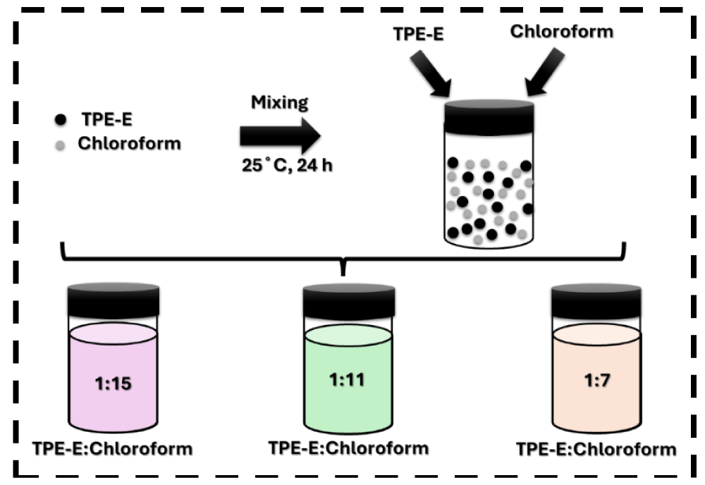
To investigate the electrospinning performance and fiber formation morphology, 3 different solutions at different polymer: solvent (P:S) weight ratios were prepared as 1:15, 1:11, and 1:7 as given in Figure 1. The concentration of the solutions was calculated as 6.25, 8.3 and 12.5 wt% for P:S values of 1:15, 1:11 and 1:7, respectively. Mixtures were mixed at room temperature (25 °C) for about 24 hours by a magnetic stirrer until complete polymer dissolution and clear solutions were obtained.
Electrospinning systems and process conditions
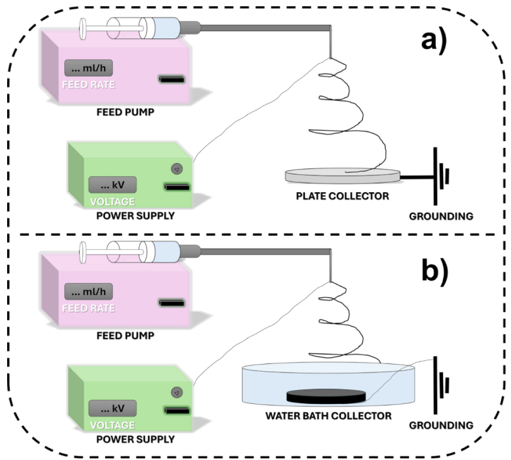
Electrospinning was carried out by two different systems. The first system was a traditional system with a plate collector as given in Figure 2a and referred to dry electrospinning spinning (DS). For the second system, only the collector was changed to a water bath and spinning was performed vertically as shown in Figure 2b. The system was referred to as wet electrospinning (WS). Table salt was added to water to increase the conductivity of the bath with a concentration of around 3 wt% NaCl. Sample codes, properties of solutions, and electrospinning conditions of DS and WS were given in Tables 1,2, respectively. During electrospinning, regardless of the solution content, feed rate values were set as 1- and 3-ml h-1, and applied voltage values were set as 10, 15, and 20 kV.
Characterization
Solution viscosity: A Brookfield DV2T viscometer was used for the determination of the viscosity of spinning solutions. The measurements were performed at 200 rpm with spindle #3 at room temperature (25 °C, %50 RH).
Morphological analysis: A digital binocular compound microscope (AmScope 40X-2500X LED) was used for fiber morphology analysis. Fiber diameter and bead size distributions of the samples were determined by using the data obtained by Image J software, and average and standard deviation (SD) were calculated.
Results and Discussions
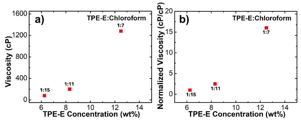
Solution viscosity is an important parameter for the spinning process since it reflects the resistance of the spinning jet to flow from needle to collector under an electrical field. Additionally, it is of importance for fiber morphology. In this work, three different electrospinning solutions were prepared at different polymer: solvent weight ratios such as 1:7, 1:11, and 1:15 to find the optimum solution concentration. The solution viscosity values were determined as 1280, 200, and 80 cP for 1:7 (12.5 wt%), 1:11(8.3 wt%), and 1:15 (6.25 wt%), respectively, and given in Figure 3a. Parallel with previous studies, increased amount of polymer amount resulted in higher viscosity due to higher entanglement caused by a higher level of molecular interactions [11].
Normalized viscosity (NV) values of the solutions were calculated by using the equation (NV=η/ηl). η was the viscosity of the solution and ηl was the lowest solution viscosity (η1:15). NV values given in Figure 3b were determined as 16, 2.5, and 1 for TPE-E: Chloroform solutions with the ratio of 1:7, 1:11 and 1:15, respectively. Although the increase was slight between 1:15 and 1:11; it is 25 times higher between 1:15 and 1:7. This also indicates a higher level of molecular interactions at higher polymer concentrations.
Morphological analysis
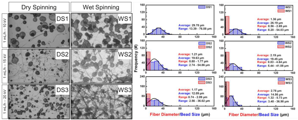
Morphologies of electrospun fibers were evaluated based on their processing conditions and collector type. Each figure (Figures 4-9) represents electrospun fibers collected by plate and water bath collectors at a constant needle-collector distance, solution concentration, and feed rate under various applied voltage values. As given in Tables 1,2, morphologies of samples were analyzed by considering fiber/bead formation and average fiber/bead diameter. Additionally, SD values were given in the parenthesis. Optical microscope images of samples with the P:S ratio of 1:15, those electrospun at 1 mL h-1 feed rate under 10, 15, and 20 kV with plate and water bath collectors were given in Figure 4. Samples prepared by the plate collector showed mostly bead morphology. There was almost no fiber formation at 10 kV (DS1). DS2 and DS3 dominantly showed beads and negligible fiber networks. The average fiber/bead (F/B) diameter values of DS1, DS2, and DS3 were measured as -/29.78, 1.21/19.63, and 1.17/12.09 µm, respectively. As seen from the results, increased voltage led to the formation of finer fiber networks and smaller beads due to a higher stretching effect under higher voltages [11] regardless of the collector type. Samples prepared by a water bath collector showed slightly fibrous networks even at 10 kV and fiber formation became more dominant by increasing applied voltage, especially at 20 kV. However, in all cases, beads can be observed easily. The average F/B diameter values of WS1, WS2, and WS3 were measured as 1.36/26.19, 2.19/19.45, and 2.78/14.56 µm, respectively. As can be seen from the results, increased voltage led to the formation of smaller beads and thicker fiber networks. Although no condition ensured bead bead-free fiber mat for both collectors, a water bath collector under 20 kV was found as the optimum setting in terms of fiber formation.
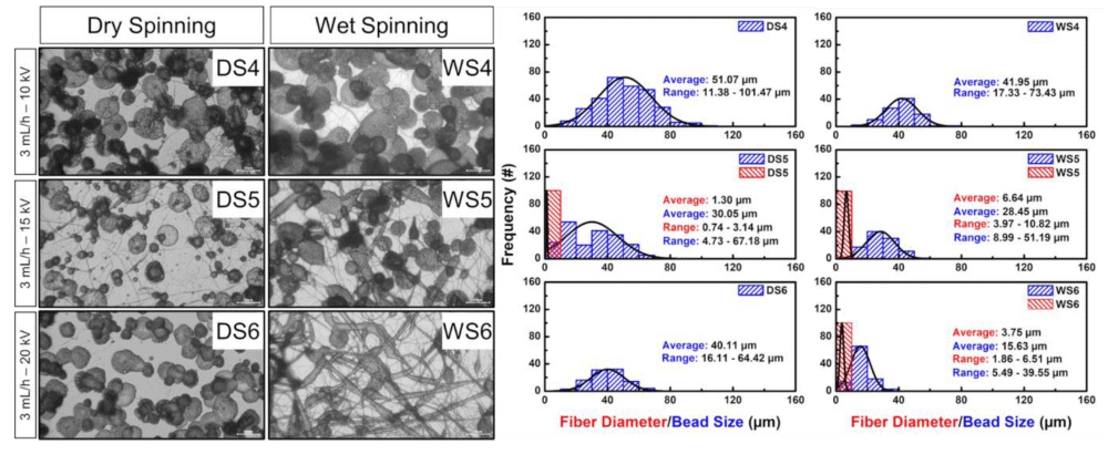
Optical microscope images of samples with the P:S ratio of 1:15, those electrospun at 3 mL h-1 feed rate under 10, 15, and 20 kV with plate and water bath collectors were given in Figure 5. As obvious from the images, samples mostly consisted of beads only DS5 had negligible fiber networks. The average fiber/bead (F/B) diameter values of DS4, DS5, and DS6 were measured as -/51.07, 1.3/30.05, and -/40.11µm, respectively. When this set was compared with DS1-DS3, it was seen that fiber formation was not observed even if at a higher feed rate. Samples prepared by a water bath collector showed slightly fibrous networks at 15 kV and 20 kV fiber formation became more obvious. However, in all cases, beads can be observed easily. The average F/B diameter values of WS4, WS5, and WS6 were measured as -/41.95, 6.64/28.45, and 3.75/15.63 µm, respectively, and increased voltage led to the formation of smaller beads and thicker fiber networks. Since the bead formation was hindered at higher voltages polymer solution was used more effectively for the formation of thicker fibers. This set was found to show smaller beads and thicker fibers compared to the WS1-WS3 set which was probably caused by a higher feed rate [35]. Although no condition ensures bead bead-free fiber mat for both collectors, a water bath collector at 20 kV was found as the optimum setting in terms of fiber formation.
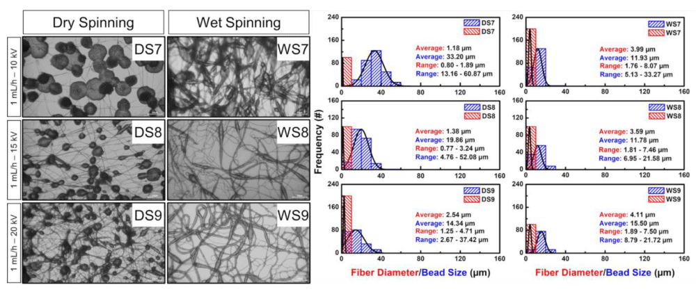
Optical microscope images of samples with the P:S ratio of 1:11, those electrospun at 1 mL h-1 feed rate under 10, 15, and 20 kV with plate and water bath collectors were given in Figure 6. As obvious from the images, samples consisted of beads and fiber networks. The average fiber/bead (F/B) diameter values of DS7, DS8, and DS9 were measured as 1.18/33.20, 1.38/19.86, and 2.54/14.34 µm, respectively. When this set was compared with DS1-DS3, the polymer concentration effect can be seen easily. As can be seen from viscosity and normalized viscosity data (Figure 3b) the viscosity of the P:S 1:11 solution was 2.5 times higher than the P:S 1:15 solution. As a rule, increased polymer concentration resulted in higher viscosity due to higher entanglement caused by higher levels of molecular interactions and fiber formation is more pronounced for this set (DS7-DS9) [36]. Samples prepared by a water bath collector showed fibrous networks regardless of the applied voltage. While beads were more spherical at low voltage, bead morphology turned into elliptical geometry (spindle-like) at higher voltage values. The average F/B diameter values of WS7, WS8, and WS9 were measured as 3.99/11.93, 3.59/11.78 and 4.11/15.50 µm, respectively. This set was found to show smaller beads and thicker fibers compared to the WS1-WS3 set, likely due to the higher solution viscosity necessary for fiber formation. In addition, the viscoelastic behavior of polymer solutions also explains these findings. The polymer chains remain suitably isolated and do not overlap in dilute solutions. However, above the critical polymer concentration, entanglements between macromolecules lead to a significant increase in viscosity [37,38]. Optimum settings in terms of fiber formation were obtained for the water bath collector under both 15 and 20 kV.
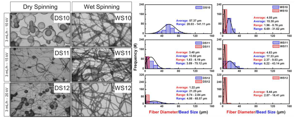
Optical microscope images of samples with the P:S ratio of 1:11, those electrospun at 3 mL h-1 feed rate under 10, 15, and 20 kV with plate and water bath collectors were given in Figure 7. As obvious from the images, DS10 was full of beads, fibrous network formation was observed only for DS11, and DS12 showed a mixture of beads and fibers. The average fiber/bead (F/B) diameter values of DS10, DS11, and DS12 were measured as -/57.37, 3.40/13.92, and 1.22/21.25 µm, respectively. When this set was compared with DS4-DS6, the polymer concentration effect can be noticed. Higher solution viscosity and higher entanglement led to a higher level of fiber formation for DS10-DS12 [37]. Samples prepared by a water bath collector showed fibrous networks regardless of the applied voltage. WS10 and 11 showed elliptical beads in the fibrous network and WS12 showed bead-free morphology. The average F/B diameter values of WS10, WS11, and WS12 were measured as 4.55/15.38, 4.83/17.33, and 5.44/- µm, respectively. This set was found to show smaller beads and thicker fibers compared to the WS4-WS7 set which was caused by higher solution viscosity [37]. Uniform fibers were obtained with a water bath collector under 20 kV.
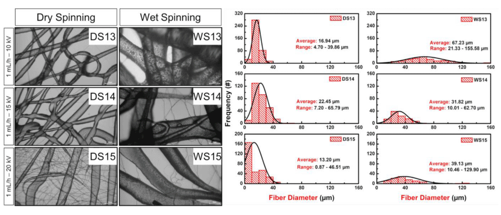
Optical microscope images of samples with the P:S ratio of 1:7, those electrospun at 1 mL h-1 feed rate under 10, 15, and 20 kV with plate and water bath collectors were given in Figure 8. As seen from the images, all samples showed fiber morphology. The average fiber diameter values of DS13, DS14, and DS15 were measured as 16.94, 22.45, and 13.20 µm, respectively. To analyze the solution concentration, this set was compared with DS1-3 and DS7-9. Since the viscosity of P:S 1:7 was 6.4 and 16 times more than P:S 1:11 and P:S 1:15, respectively, fiber diameter values were remarkably higher. Samples prepared by a water bath collector showed fibrous networks under all voltage values. The average fiber diameter values of WS13, WS14, and WS15 were measured as 67.23, 31.82 and 39.13 µm, respectively. Increased voltage led to the formation of finer fibers due to a higher stretching effect. To analyze the solution concentration effect, this set was compared with WS1-3 and WS7-9. Parallel with the results obtained from the plate collector, higher solution viscosity led to the formation of thicker fibers. Regardless of the collector type and applied voltage fiber morphology was observed for all samples. However, more uniform fibers were obtained when the plate collector was used under 10 and 15 kV. The water bath collector led to formation of thicker fibers. This could be possible in two ways: 1) differences in the electrical field and 2) collector-polymer jet interactions. While fibers covered a larger area on the plate collector; fibers tend to cover a smaller area in the water bath due to changes in electrical field. In this way the total distance that a random jet travels from needle to collector was longer for dry spinning and the polymer jet was exposed to a higher level of stretching. Because of that, the plate collector resulted in the formation of fine fibers [39,40]. Another important parameter for these diameter differences could be the rheological behavior of the TPE-E polymer solution. During the electrospinning process, polymer jets were stretched in the air, hit the collector, and collected as fibers with some residual stress. When the collector had a solid and rough surface, stress relaxation of fiber occurred in time, and couldn’t affect fiber morphology. On the other hand, when the polymer jet hit the water bath collector, the residual stress accumulated in the fiber was relaxed suddenly and elastic recovery occurred due to both the elastic nature of TPE-E polymer solutions and the liquid nature of the water bath collector. Because of that, the water bath collector resulted in the formation of coarse fibers [41,42].
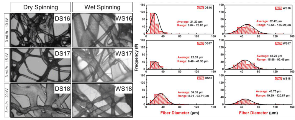
Optical microscope images of samples with the P:S ratio of 1:7, those electrospun at 3 mL h-1 feed rate under 10, 15, and 20 kV with plate and water bath collectors were given in Figure 9. As seen from the images, DS16-DS18 showed fiber morphology. The average fiber diameter values of DS16, DS17, and DS18 were measured as 21.23, 22.39, and 34.32 µm, respectively. Compared to the 1 mL h-1 feed rate, fiber diameter increased drastically. As expected, this set showed higher fiber diameter compared to DS4-6 and DS10-12 due to higher solution viscosity. Samples prepared by a water bath collector showed average fiber diameter values of 52.42, 48.20, and 48.75 µm for WS16, WS17, and WS18, respectively. Higher voltage resulted in finer fiber formation. When this set was compared with WS4-6 and WS10-12 it was observed that high viscosity caused the formation of thicker fibers. As in the 1 mL h-1 feeding rate, fiber morphology was obtained regardless of the collector type and applied voltage. However, thinner fibers with higher uniformity were obtained when a plate collector was used as explained previously.
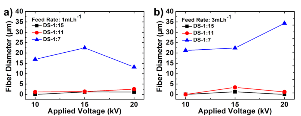
As shown in Figure 10, solution viscosity and applied voltage were found critical for fiber formation and average diameter for dry spinning. For both feed rates, the highest viscosity resulted in higher fiber diameter. Although the applied voltage effect was not pronounced for P: S=1:15, 1:11; it was found significant at 1:7, and higher applied voltage led to a decrease in fiber diameter.
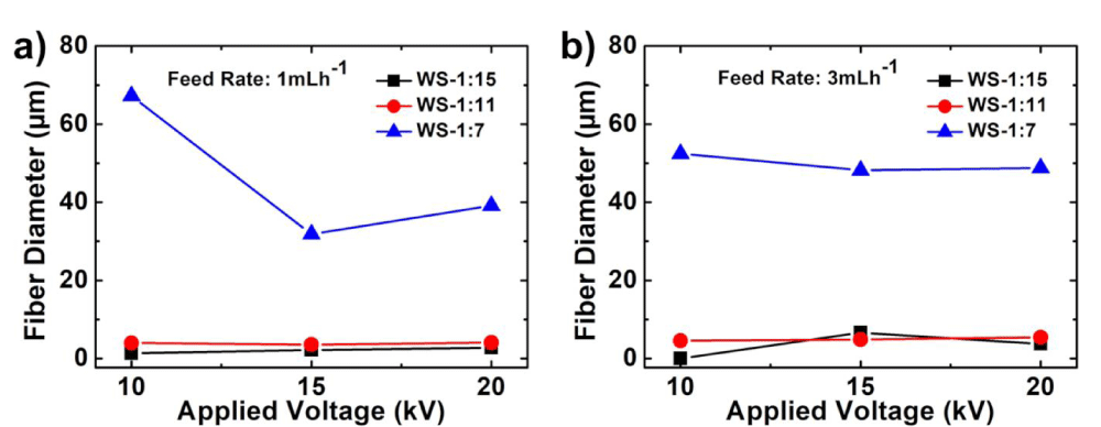
As shown in Figure 11, solution viscosity, feed rate, and applied voltage were found critical for fiber formation and average diameter for wet spinning. For both feed rates, the highest viscosity resulted in higher fiber diameter. Although the applied voltage effect was not pronounced for P: S=1:15, 1:11; it was found significant at 1:7 at 1 mL h-1 feed rate.
From the results, it is possible to change and control the morphology of the final product from uniformly Distributed Spherical Beads (DS1) to fibers (WS12) by changing solution parameters or process conditions in electrospinning. Solution concentration and therefore solution viscosity are the most critical parameters for this change, especially by using TPE-E polymers. By adding and distributing nanoparticles into TPE-E polymer solution, it is also possible to create much more sophisticated morphologies such as dendritic nano-trees [15], nailed-bat-like structures [43], etc. Future work could further enhance these fibers by embedding nanoparticles within the fiber matrix, thereby potentially improving mechanical properties, electrical conductivity, and functional performance, and expanding the application range of electrospun fibers to include advanced filtration systems, sensors, high-performance textiles, and biomedical devices [30,44].
Conclusion
In this study electrospinning of thermoplastic polyester elastomer fibers by using different collectors was performed for the first time in literature. To optimize the electrospun TPE-E fibers, three different polymer solutions were prepared with the polymer: solvent ratios as 1:7, 1:11, and 1:15. The polymer solution was fed with a flow rate of 1, 3 ml h-1 under 10, 15, and 20 kV. Fibers were collected on the plate and water bath collectors. According to the outcomes of this study, electrospinning parameters including solution viscosity, solution feed rate, applied voltage, and collector type have an important effect on the fiber morphology. Solution viscosity was critical for fiber formation and the average diameter and uniformity of the fibers. For both collectors, the viscosity of the solution with the ratio of P: S=1:15 was not found sufficient for fiber formation. P: S=1:11 ratio was found spinnable for the water bath collector and P: S=1:7 was spinnable for both collectors. Additionally, higher solution viscosity generally resulted in higher fiber diameter. Also, feed rate and applied voltage were found to be significant in some cases in terms of fiber formation (such as wet spinning at 1 mL h-1). Another important electrospinning parameter was found as collector type in terms of fiber formation and morphology. Generally, the water bath collector led to formation of thicker fibers. The most uniform fibers were identified as DS13, DS14, DS17 and WS12. Overall, tunable fiber morphology can be achieved by varying the spinning solution concentration and processing conditions. These findings underscore the importance of carefully controlling electrospinning parameters to achieve desired fiber characteristics in thermoplastic polyester elastomer applications.
This project was funded by Yalova University, BAP (Scientific Research Project) Project No: 2023/YL/0008 and The Scientific and Technological Research Council of Turkey (TUBITAK) 2210-C National Graduate Scholarship Program in High Priority Technological Areas.
- Bhowmick AK, ed. Current topics in elastomers research. 1st ed. Boca Raton: CRC Press; 2008.
- Fakirov S. Handbook of Condensation Thermoplastic Elastomers. 2006.
- Kear K. Developments in thermoplastic elastomers. Rapra Review 2003; 14(10):1–141.
- McKeen LW. The effect of creep and other time related factors on plastics and elastomers. 2014.
- Drobny JG. Handbook of Thermoplastic Elastomers: Second Edition. 2014.
- Coleman D. Block copolymers: Copolymerization of ethylene terephthalate and polyoxyethylene glycols. J Polym Sci 1954; 14(73):15–28. doi:10.1002/pol.1954.120147303.
- Li H, White JL. Structure development in melt spinning filaments from polybutylene terephthalate based thermoplastic elastomers. Polym Eng Sci 2000; 40(4):917–928. doi:10.1002/pen.11219.
- Kwak SY, Nakajima N. Morphology formation in mixing of copolyester thermoplastic elastomer (hytrel) with poly(vinyl chloride) and nuclear magnetic resonance relaxation study on solid structures of the mixture. Macromolecules 1996; 29(10):3521–3524. doi:10.1021/ma951117o.
- Pandey N, Tewari C, Dhali S, et al. Effect of graphene oxide on the mechanical and thermal properties of graphene oxide/hytrel nanocomposites. J Thermoplast Compos Mater 2021; 34(1):55–67. doi:10.1177/0892705719838010.
- Pearson A, Liao W, Heydrich M, et al. Role of interfacial adhesion and fiber length on the mechanical performance fiber reinforced thermoplastic elastomers. Compos Sci Technol 2021; 213:108928. doi:10.1016/j.compscitech.2021.108928.
- Cao D, Fu Z, Li C. Electrospun fiber membranes of novel thermoplastic polyester elastomers: Preparation and characterization. J Appl Polym Sci 2011; 122(3):1698–1706. doi:10.1002/app.34024.
- Zhao Y, Chen R, Ni R, Liu H, Li J, Huang C. Fabrication and characterization of a novel facial mask substrates based on thermoplastic polyester elastomer fibers. J Text Inst 2020; 111(8):1231–1237. doi:10.1080/00405000.2019.1702612.
- Abhiraman AS, Kim YW, Wagener KB. Evolution of structure and properties in fiber formation from a thermoplastic polyester‐polyether segmented copolymer. J Polym Sci B Polym Phys 1987; 25(1):205–228. doi:10.1002/polb.1987.090250116.
- Zhu F, Xin Q, Feng Q, Zhou Y, Liu R. Novel poly(vinylidene fluoride)/thermoplastic polyester elastomer composite membrane prepared by the electrospinning of nanofibers onto a dense membrane substrate for protective textiles. J Appl Polym Sci 2015; 132(26):42170. doi:10.1002/app.42170.
- Lim GT, Puskas JE, Reneker DH, Jákli A, Horton WE Jr. Highly hydrophobic electrospun fiber mats from polyisobutylene-based thermoplastic elastomers. Biomacromolecules. 2011 May 9;12(5):1795-9. doi: 10.1021/bm200157b. Epub 2011 Apr 19. PMID: 21449616.
- Baudis S, Ligon SC, Seidler K, et al. Hard-block degradable thermoplastic urethane-elastomers for electrospun vascular prostheses. J Polym Sci A Polym Chem 2012; 50(7):1272–1280. doi:10.1002/pola.25887.
- Pritchard CD, Arnér KM, Langer RS, Ghosh FK. Retinal transplantation using surface modified poly(glycerol-co-sebacic acid) membranes. Biomaterials. 2010 Nov;31(31):7978-84. doi: 10.1016/j.biomaterials.2010.07.026. Epub 2010 Jul 24. PMID: 20656341; PMCID: PMC4059040.
- Pritchard CD, Arnér KM, Neal RA, et al. The use of surface modified poly(glycerol-co-sebacic acid) in retinal transplantation. Biomaterials 2010; 31(8):2153–2162. doi:10.1016/j.biomaterials.2009.11.074.
- Kwon IK, Kidoaki S, Matsuda T. Electrospun nano- to microfiber fabrics made of biodegradable copolyesters: structural characteristics, mechanical properties and cell adhesion potential. Biomaterials. 2005 Jun;26(18):3929-39. doi: 10.1016/j.biomaterials.2004.10.007. PMID: 15626440.
- Jin J, Jeong SI, Shin YM, Lim KS, Shin Hs, Lee YM, Koh HC, Kim KS. Transplantation of mesenchymal stem cells within a poly(lactide-co-epsilon-caprolactone) scaffold improves cardiac function in a rat myocardial infarction model. Eur J Heart Fail. 2009 Feb;11(2):147-53. doi: 10.1093/eurjhf/hfn017. PMID: 19168512; PMCID: PMC2639416.
- Masoumi N, Annabi N, Assmann A, Larson BL, Hjortnaes J, Alemdar N, Kharaziha M, Manning KB, Mayer JE Jr, Khademhosseini A. Tri-layered elastomeric scaffolds for engineering heart valve leaflets. Biomaterials. 2014 Sep;35(27):7774-85. doi: 10.1016/j.biomaterials.2014.04.039. Epub 2014 Jun 16. PMID: 24947233; PMCID: PMC4114056.
- Bhuyan P, Singh M, Wei Y, et al. Thread-analogous elastic fibers with liquid metal core by drawing at room temperature for multifunctional smart textiles. Chem Eng J 2024; 480:147944. doi:10.1016/j.cej.2023.147944.
- Zheng L, Zhu M, Wu B, Li Z, Sun S, Wu P. Conductance-stable liquid metal sheath-core microfibers for stretchy smart fabrics and self-powered sensing. Sci Adv. 2021 May 28;7(22):eabg4041. doi: 10.1126/sciadv.abg4041. PMID: 34049879; PMCID: PMC8163087.
- Park S, Baugh N, Shah HK, Parekh DP, Joshipura ID, Dickey MD. Ultrastretchable Elastic Shape Memory Fibers with Electrical Conductivity. Adv Sci 2019; 6(21):1901579. doi:10.1002/advs.201901579.
- Uribe-Gomez J, Schönfeld D, Posada-Murcia A, Roland MM, Caspari A, Synytska A, Salehi S, Pretsch T, Ionov L. Fibrous Scaffolds for Muscle Tissue Engineering Based on Touch-Spun Poly(Ester-Urethane) Elastomer. Macromol Biosci. 2022 Apr;22(4):e2100427. doi: 10.1002/mabi.202100427. Epub 2022 Jan 17. PMID: 35007398.
- Jindal A, Molnár K, McClain A, Paiva dos Santos B, Camassola M, Puskas JE. Electrospun fiber mats from poly(alloocimene-b-isobutylene-b-alloocimene) thermoplastic elastomer. Int J Polym Mater Polym Biomater 2020; 69(4):263–267. doi:10.1080/00914037.2018.1563083.
- Khadse N, Ruckdashel R, Macajoux S, Sun H, Park JH. Temperature Responsive PBT Bicomponent Fibers for Dynamic Thermal Insulation. Polymers (Basel). 2022 Jul 6;14(14):2757. doi: 10.3390/polym14142757. PMID: 35890533; PMCID: PMC9323749.
- Hossain KZ, Khan MR. Computer-Aided Engineering of Stretchable Hollow Fibers to Enable Wearable Microfluidics. Adv Mater Technol 2023; 8(18):2300682. doi:10.1002/admt.202300682.
- Wu S, Dong T, Li Y, Sun M, Qi Y, Liu J, Kuss MA, Chen S, Duan B. State-of-the-art review of advanced electrospun nanofiber yarn-based textiles for biomedical applications. Appl Mater Today. 2022 Jun;27:101473. doi: 10.1016/j.apmt.2022.101473. Epub 2022 Apr 10. PMID: 35434263; PMCID: PMC8994858.
- Ye H, Zhang K, Kai D, Li Z, Loh XJ. Polyester elastomers for soft tissue engineering. Chem Soc Rev 2018; 47(12):4545–4580. doi:10.1039/C8CS00161H.
- Li Y, Zhu J, Cheng H, et al. Developments of Advanced Electrospinning Techniques: A Critical Review. Adv Mater Technol 2021; 6(11):2100410. doi:10.1002/admt.202100410.
- Agarwal S, Greiner A. On the way to clean and safe electrospinning—green electrospinning: emulsion and suspension electrospinning. Polym Adv Technol 2011; 22(3):372–378. doi:10.1002/pat.1883.
- Khorshidi S, Solouk A, Mirzadeh H, Mazinani S, Lagaron JM, Sharifi S, Ramakrishna S. A review of key challenges of electrospun scaffolds for tissue-engineering applications. J Tissue Eng Regen Med. 2016 Sep;10(9):715-38. doi: 10.1002/term.1978. Epub 2015 Jan 26. PMID: 25619820.
- Ahmed FE, Lalia BS, Hashaikeh R. A review on electrospinning for membrane fabrication: Challenges and applications. Desalination 2015; 356:15–30. doi:10.1016/j.desal.2014.09.033.
- Zhao L, He C, Gao Y, Cen L, Cui L, Cao Y. Preparation and cytocompatibility of PLGA scaffolds with controllable fiber morphology and diameter using electrospinning method. J Biomed Mater Res B Appl Biomater. 2008 Oct;87(1):26-34. doi: 10.1002/jbm.b.31060. PMID: 18384158.
- Chuangchote S, Sirivat A, Supaphol P. Electrospinning of Styrene-Isoprene Copolymeric Thermoplastic Elastomers. Polym J 2006; 38(9):961–969. doi:10.1295/polymj.PJ2005234.
- Gupta P, Elkins C, Long TE, Wilkes GL. Electrospinning of linear homopolymers of poly(methyl methacrylate): exploring relationships between fiber formation, viscosity, molecular weight and concentration in a good solvent. Polymer (Guildf) 2005; 46(13):4799–4810. doi:10.1016/j.polymer.2005.04.021.
- Hsu C-M, Shivkumar S. Nano-sized beads and porous fiber constructs of Poly(ε-caprolactone) produced by electrospinning. J Mater Sci 2004; 39(9):3003–3013. doi:10.1023/B.0000025826.36080.cf.
- Kong CS, Lee TH, Lee SH, Kim HS. Nano-web formation by the electrospinning at various electric fields. J Mater Sci 2007; 42(19):8106–8112. doi:10.1007/s10853-007-1734-3.
- Röcker T, Greiner A. Electrospinning of poly-L-lactide nanofibers on liquid reservoir collectors. e-Polymers 2008; 8(1):111. doi:10.1515/epoly.2008.8.1.1268.
- Li W, Xu L, Wang X, Zhu R, Yan Y. Phase Change Energy Storage Elastic Fiber: A Simple Route to Personal Thermal Management. Polymers (Basel). 2021 Dec 24;14(1):53. doi: 10.3390/polym14010053. PMID: 35012076; PMCID: PMC8747497.
- Cho SJ, Nam H, Ryu H, Lim G. A Rubberlike Stretchable Fibrous Membrane with Anti-Wettability and Gas Breathability. Adv Funct Mater 2013; 23(45):5577–5584. doi:10.1002/adfm.201300442.
- Karahan Toprakci HA, Turgut A, Toprakci O. Nailed-bat like halloysite nanotube filled polyamide 6,6 nanofibers by electrospinning. Polym Plast Technol Mater 2021; 60(5):522–535. doi:10.1080/25740881.2020.1819313.
- Mao Y, Shen W, Wu S, et al. Electrospun polymers: Using devices to enhance their potential for biomedical applications. React Funct Polym 2023; 186:105568. doi:10.1016/j.reactfunctpolym.2023.105568..

Article Alerts
Subscribe to our articles alerts and stay tuned.
 This work is licensed under a Creative Commons Attribution 4.0 International License.

 Save to Mendeley
